6. Core Pipeline
This chapter discusses the micro-architecture and features of the core pipeline. The core pipeline consists of the following stages:
Program Counter Generation Stage (PC Gen)
Instruction Fetch Stage (IFS)
Decode Stage
Execution Stage
Memory Stage
Write Back Stage
The following sections provide specific details of each stage.
The pipeline diagram is shown in Fig. 6.1
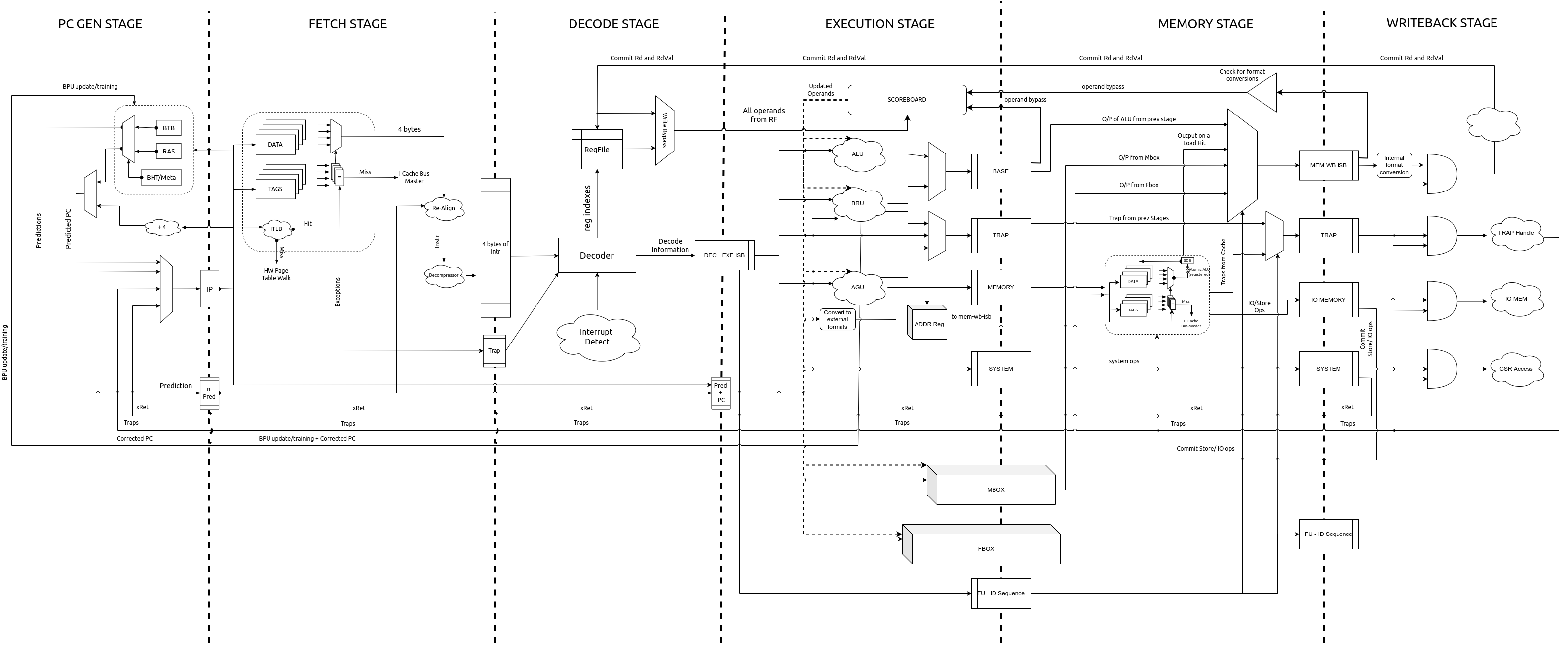
Fig. 6.1 Pipeline Diagram
6.1. PC Gen Stage [stage0.bsv]
The PC Gen stage is responsible for generating the next value of the PC to be fetched. Once reset is
de-asserted and the reset_sequence is complete, the PC register in this module is assigned
the value of reset-pc (an input to the module). All other functionality only takes action after
this initialization is done.
All PCs are virtual/logical addresses. The translation of these into physical addresses is carried out by the Translation Lookaside Buffers (TLBs) and Page Table Walk (PTW) units in the Instruction Memory Subsystem (IMS). The translation is based on the supervisor spec defined in the RISC-V Privileged Spec.
The PC Gen stage also includes, an optional (chosen at design time), Branch Predictor Unit (BPU) for predictive conditional/unconditional control instructions for improved performance. The BPU can be enabled/disabled at runtime through the custom control CSR (Section 8.1).
Tip
Disabling the BPU can prove to be useful for more deterministic and secure execution environments.
While the next value of the PC is determined, the current value of the PC is fed into the Instruction Memory Subsystem (IMS), and forwarded to the IFS as well. Information about the prediction of the current PC in from the BPU is also passed on to the IFS.
6.1.1. Next PC Generation
The Next PC source can be any of the following:
Default: by default the next PC is assigned as PC + 4.
2. Cache-line Straddle: When compressed extension is enabled, the PC can be 2 byte aligned. In a case where the current PC points to the last word in a cacheline and the last word contains a compressed and a part of uncompressed instruction which straddles across a cacheline, the next PC generated needs to be PC+2 (as the responses are cacheline sized). This causes no problems when the PC of the next instruction in the program flow is PC+2 or PC+4. However, if there is a redirection (jump/branch) at the current PC from the branch prediction unit, the predicted target is stored in an intermediate register while PC+4 is passed on as next PC. The predicted target is then selected as next PC, subsequently.
3. Trap redirection: If the write-back stage takes a trap (due to interrupts, exceptions, environment calls, etc), then the next PC is set to the value available in the corresponding trap vector CSR (Control and Status Register) which is supplied by the write-back stage itself.
4. Control instruction resolution: When control instructions (branches, jumps, calls and returns) are resolved in the pipeline, the execution stage indicates a re-direction of the PC while providing the target address. When BPU is enabled, only mispredictions of control instructions detected in the execution stage cause a re-direction request to the PC-Gen stage.
5. Internal Re-directions: CSR instructions and fence.i/sfence.vma instructions cause the next instruction to be fetched again. The PC of the next instruction is provided by the write-back stage.
6. Branch Prediction: When the BPU is enabled, it predicts if the current PC points to a control instruction and computes the next PC. If the branch predictor predicts that a control instruction is taken, then the next PC is assigned to the target address provided by the BPU.
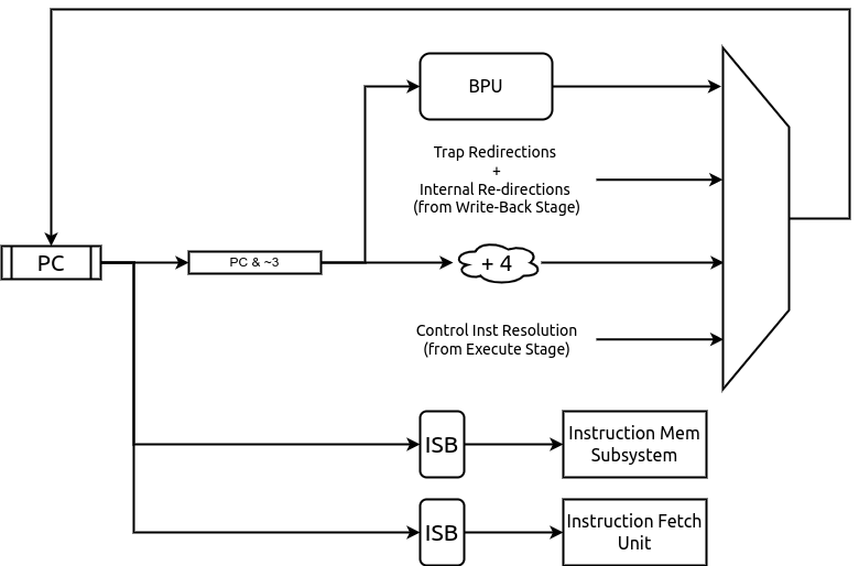
Fig. 6.2 PC Gen Stage Block diagram
6.1.2. Handling Fence Ops
When a fence.i or sfence.vma instruction reaches the write-back stage it initiates a re-fetch of the
subsequent instruction and causes the pipeline to flush. When this flush signal is received by the PC Gen
stage, it forwards the fence.i/sfence.vma request to the IMS in the subsequent cycle.
In the next cycle, the new PC arrived with the flush, is passed (after re-adjustment as described in
pc_alignment) to the IMS and the IFS.
When the branch predictor is enabled and a fence.i flush is received, then the entries in the BPU are also flushed. In case of a sfence.vma flush, the predictor is idle when the sfence.vma is being forwarded to the IMS
6.1.3. PC-Alignment
The logical address sent to the IMS and IFC can be 2-byte aligned or 4-byte aligned. A 2-byte aligned address is sent to the IMS only when the PC is a direct result from a redirection. The next addresses are always 4-byte aligned.
6.1.4. Enqueuing Packets
The PC Gen Stage feeds information/data to the IMS and the instruction fetch stage. A fence.i or sfence.vma request is sent only to the IMS and not to the instruction fetch stage as the IMS is not expected to respond to fence.i/sfence.vma ops.
In general, information/data can be sent to the IMS or the instruction fetch stage only when neither of the two are stalling and are capable of accepting new packets.
6.1.5. Branch Prediction Unit
To improve performance, a gshare based global branch predictor is implemented. It consists of a fully-associative Branch Target Buffer (BTB) with 32 entries, a 512 entry Branch History Table (BHT) and a 8 entry Return Address Stack (RAS). All of which is configurable at compile time by setting the branch_predictor parameters.
Note
Each of the parameters above are configurable at design time.

Fig. 6.3 Branch Predictor Unit
The BTB is trained with all control instructions (conditional and unconditional), but holds the target only for conditional branches and CALL instructions. The target addresses for RET instructions are maintained in the RAS.
The fully associative BTB leverages the one-hot indexing mechanism to achieve higher frequency closure. A basic round-robin replacement policy is employed by the BTB. Each entry in the BTB holds the following fields:
The logical PC pointing to a control instruction
The target PC where the next PC should re-direct to
A 2-bit field indicating the type of the control instruction: CALL, RET, JAL or BRANCH
A valid bit indicating if the entry is valid.
A boolean field indicating if the logical PC contains a 16 bit control instruction
A boolean field indicating if the logical PC starts at a 2-byte boundary. This is used to calculate the next return address for a CALL instruction.
During the prediction phase when a new PC is provided, the BPU performs a lookup in the BTB. On a hit in the BTB, the control instruction type is checked. If the instruction type is RET then the target PC is obtained (and removed) from the RAS else the target PC is picked from the BTB entry itself. When a CALL instruction is encountered, the immediate next PC value is pushed into the RAS. When compressed extension is supported, the offset of the PC to be pushed in to the RAS in case of a CALL instruction is calculated depending on whether it was a 2-byte or a 4-byte instruction starting at a 2-byte or a 4-byte boundary. This information is stored in the BTB fields as mentioned above.
Each entry in the BHT table holds a 2-bit counter variable indicating a conditional branch should be taken or not-taken. The MSB specifies the prediction and the LSB specifies the hysteresis (how “strong” the prediction is). The state machine for the update of the BHT entries is shown in Fig. 6.4. This update happens at the time of the branch resolution in the execution stage.
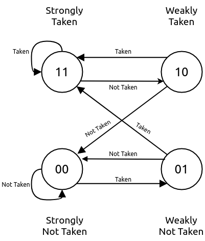
Fig. 6.4 The Two bit counter state machine.
The core uses a 8-bit history register (configurable at compile time). This register is passed along the pipe upto the execution stage for the purpose of rolling back in case of a mis prediction. During the prediction phase, the BHT table is indexed using a hash function of the PC and the history register. When the BTB is a hit and the control instruction is of BRANCH type, the BHT table entry dictates if the branch is taken or not-taken.
When a control instruction reaches the execution stage, it sends feedback on whether the prediction of the control instruction was correct or not. In case of a misprediction, if the PC does not exist in the BTB already then it is allocated a new entry and the BHT table is updated if the control instruction is a branch. If the entry already exists then only the BHT is updated for a branch instruction. On a misprediction the history register is also rolled back.
When compressed extension is enabled, the BPU provides 2 predictions, one for PC and another for PC + 2. This is done by splitting the total BHT entries into 2 banks which are selected by the LSB bit of the hash function.
Note
When a fence.i instruction is executed by the pipeline, all entries in the BTB are invalidated.
6.2. Instruction Fetch Stage (IFS) [stage1.bsv]
This stage interacts with PC Gen stage and the IMS to send a 32-bit instruction to the decode stage.
The IFS receives the following information from the PC Gen Stage:
The PC value
Boolean value indicating if the current packet should be dropped. This is set when the PC Gen Stage sends an additional PC value to the IMS to ensure that the next 2 bytes of an instruction can be fetched.
Prediction information from the BPU (which is used and passed onto the next stage for resolution).
The IFS receives the following from the IMS:
cacheline sized chunk of the instruction memory based on the address provided by the PC Gen stage
A boolean value indicating if a trap occurred during the fetch.
A 6-bit field indicating the cause value of the trap (if occurred).
When the compressed extension is enabled, this stage automatically sets the lower 2 bits of the PC
using a small state machine as shown in Fig. 6.5, where compressed
indicates whether the current instruction decoded is a compressed instruction and align is
equal to the lower 2 bits of the PC from the previous stage.
The word is extracted from the cache response based
on this PC. The PC here can be 2 byte aligned due to one of the following scenarios:
PC from stage-0 is 2 byte aligned (due to a redirection)
Last PC was 4-byte aligned and the last instruction was a compressed instruction
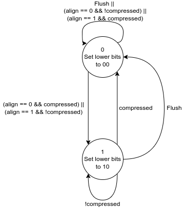
Fig. 6.5 State machine for the internal state in IFU.
If the extracted instruction is a compressed instruction, it is decompressed to an equivalent 32-bit instruction before being passed on to the decode stage.
Note
This decompression is possible only because every instruction of the compressed ISA of the RISC-V is has an equivalent 32-bit representation. By decompressing a compressed instruction in this stage, the remaining stages in the pipeline have to be modified minimallu to support the compressed extension.
Traps and their corresponding cause values are simply buffered and sent to the next stage along with the instruction.
6.3. Decode Stage [stage2.bsv]
The decode stage is responsible for decoding the 4-bytes of instruction received from the instruction fetch stage. The decoded information is used to fetch operands from the register-file for the execution stage.
The decoder function primarily extracts the following information from the 4-bytes of instruction received:
Operand indices: Captures the index of rs1, rs2 and rd used by the instruction. In case an instruction does not use any of these, then the decoder assigns it to zero When floating-point extension is enabled, rs3 is also decoded
Immediate Value: The decoder also deduces the immediate field encoding and produces a 32 bit value.
Operand type: This field indicates the source of the operands and destination registers. rs1 could either be sourced from the register files or be assigned the value of PC. rs2 could either be sourced from the register files or be assigned the immediate value or a constant value depending on the instruction. When floating-point extension is enabled, rd could point to either the integer or the floating-point register file
Instruction Type: This field classifies the instruction into one of the following types: Arithmetic, Memory, Branch, JAL, JALR, CSR-OP, TRAP, WFI , MULDIV , FLOAT .
Function Opcode: The decoder uses the funct3 and funct7 fields of the instruction to re-encode a new 7 bit field to be used by the execution stage.
6.3.1. Register File
The decode stage maintains two individual register files: one for integer and one for floating-point registers.
Each of which includes 32 registers. The zeroth register of the integer register file is hardwired
to zero. While using the Hardfloat FPU, the floating point values are stored in recoded format.
Hence the floating point registers are flen+1 bits wide in this case. The integer register file
is always xlen bits wide. The integer register file has 2 read ports and 1 write port
while the floating-point register file requires 3 read ports and 1 write port for the current set of
instructions that are supported.
On reset, 32 cycles are used to individually reset each register to 0. During this initialization, phase the decode stage does not accept any new instruction bytes from the IFS. The initialization of the floating and register files happen in parallel and thus only 32 cycles are required to initialize both.
However, if at compile time the merged_rf configuration is enabled, then the integer and floating
point registers are both maintained as a single 64-entry registerfile, with the top 32 registers
allocated for integer and the bottom 32 for floating point. During read/write the type of
operand/destination register is used to define the MSB bit of the 6-bit index into the
merged register file. While using the hardfloat FPU, the size of the registers is max(xlen,flen+1).
Additionally, in the merged register file scenario, the reset sequences takes
64 cycles instead of 32.
6.3.2. Operand Fetch
Once the operand indices are available from the decoder, they are used to fetch the latest value of the operands from the respective register files. Based on the operand type fields, the register file values are either used or discarded. During simultaneous read-writes to the same register, the register files perform a full-bypass, i.e. the value being written in the current cycle is directly consumed by the instruction during operand fetch.
6.3.3. Trap Handling
All interrupts to the hart (local or external) are detected in the decode stage. Illegal traps and traps received from the previous stage are captured here and processed for the next stage.
When a trap is detected, the decode stage is stalled (i.e. it will no longer accept new instructions from the IFS) until a re-direction from the execute-stage or the write-back stage is received. This prevents the flooding the pipeline with more instructions when a trap re-direction is expected.
6.3.4. Micro Traps
The core also supports micro-traps (a.k.a hidden traps) which are used to carry out architecturally hidden actions by leveraing the same TRAP mechanism and artifacts throughout the pipeline. While micro traps are detected in the decode stage, their actions may be initiated all the way from the write-back stage of the pipeline. The following micro-traps are currently supported:
Rerun on CSR: When a csr operation is detected in the decode stage, the subsequent instruction in the decoder stage is tagged with a micro-trap. When this instruction reaches the write-back stage it issues a flush of the pipeline and resets pc to itself. This is done to ensure that the instruction was fetched under the new csr changes.
Rerun on FenceI: Same as above, but the instruction after a FenceI is tagged as a micro-trap. This is because fencing of the IMS only occurs when the fence.i instruction reaches the write-back stage and therefore the next fetched instruction must be fetched again.
Rerun on SFence: Same as above, but for sfence.vma instruction.
Each type of micro-trap is given a custom cause value. When a micro-trap is detected, the instruction is tagged as a TRAP instruction while an additional boolean field is set indicating that the cause must interpreted as a micro-trap cause, instead of the regular trap cause.
6.3.5. WFI Handling
When a WFI (Wait for Interrupt) instruction is detected, the decode stage is stalled from the subsequent cycle onwards. The stage resumes only when an interrupt (local or external) is detected.
6.3.6. CSR op Handling
For CSR ops, the validation of the access is performed in the decode stage. If the validation fails, the instruction is tagged as an Illegal Trap instruction
Presently, all CSR operations flush the pipeline, therefore, when a CSR instruction is detected the decode stage stalls from the subsequent cycle until a re-direction signal is received from either the execution stage or the write-back stage.
6.4. Execution Stage [stage3.bsv]
This stage encapsulates all the functional units required to initiate/complete the execution of an instruction. The Scoreboard, used for operand bypass and stalls, is also implemented in this stage. A block diagram of the stage is shown in Fig. 6.6
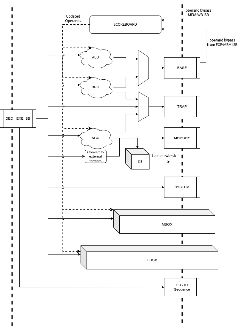
Fig. 6.6 Execution Stage of the pipeline
6.4.1. Scoreboard
This scoreboard in its minimal configuration implements a 32-bit register for each architectural register file (integer and/or floating point). Each bit in this register corresponds to a register in the respective register file. When a bit is set it indicates that there exists an instruction in the further stages of the pipeline which holds an updated value of the register which has not been committed to the register file yet. We refer to this bit as the lock_bit as shown in Fig. 6.7
When an instruction in the execution stage is dispatched for execution, the lock bit corresponding to the the destination register (except x0 of the integer register file) is set to 1 in the scoreboard. The lock bit is reset to 0 only when the instruction with the same destination register is committed in the write-back stage.
When waw_stalls is enabled during compile time, the Operand Bypass module (described below) will stall the pipeline for the instruction which has an operand whose lock bit in the scoreboard is set.
However, when waw_stalls is disabled during compile time, the scoreboard along with the lock bit maintains a id field which corresponds to a unique instruction in the pipeline which holds the latest value of the register. Thus, when performing bypass, this id is also checked to ensure that only the latest value of the operand is picked, else a stall is generated.
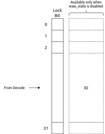
Fig. 6.7 Scoreboard Structure for the integer register file.
6.4.2. Operand Bypass
The module receives the operands from the registerfile (always holding the latest values as the registerfile acts as a bypass-registerfile). The module also has access to the current scoreboard which indicates if there exists an instruction in the further stages of the pipeline with a potentially new value of the operand.
The sources of the bypass include the head of the BASE ISB between EXE-MEM and the head of the ISB between MEM-WB. The third source of the bypass is the registerfile itself. Bypass is performed for rs1 and rs2. It is also done for rs3 when the F/D extensions are enabled.
When the hardfloat FPU is used for F/D extensions, the forwarded floating-point operands are always in the recoded format. However, for floating point loads the conversion from IEEE to recoded format happens in the Ex stage. Due to this, operand forwarding is disabled from stage 4 for a floating point load instruction thereby causing a load-to-use latency to increase by 1 cycle as compared to the integer case.
The bypass module will indicate if the respective operand is available to initiate execution or not. When waw_stalls are disabled, then checks on the bypass packets from the ISB will also include checking if the bypass register id matches the corresponding id from the scoreboard.
6.4.3. Functional Units
The execution stage is divided in multiple independently accessed functional units as shown in Fig. 6.6. Each of these functional units perform the execution of a certain subset of the instructions. The following functional units are available in the execution stage:
ALU: This executes basic arithmetic, logic and shift operations
Branch Resolution Unit (BRU): This will handle all the control instructions and the mispredictions if any
MBOX : This unit will offload the multiply and divide operations to the mbox module.
FBOX : This unit will offload the floating point operations to the fbox module.
AGU : This unit will generate the address of the memory operation and offload it to the DMS.
Based on the decoded information obtained from the head of the DEC-EXE ISB, one of the functionaly units is chosen. Only when all operands of the instruction are available is the instruction offloaded for execution to the respective functional unit.
Note that the ISBs between EXE and MEM stages is split in to multiple smaller ISBs which hold the results of different functional units. For example, the outputs of the ALU and the BRU, after execution are fed in to the BASE ISB as shown in Fig. 6.6. The output of the AGU is sent to the MEMORY ISB. System instructions (like CSR ops, xRET, etc) are directly buffered into the SYSTEM ISB.
It is possible that the BRU and AGU generate mis-aligned traps, in which case the result is enqued into the TRAP ISB. All previously decoded traps (from decode and pc-gen stages) are directly buffered into the TRAP ISB.
As soon as an instruction is offloaded to the respective functional unit, we enqueue the functional unit id into the FUID ISB. This buffer basically indicates the order in which the instructions in the further pipeline stages must be processed and committed. Simultaneously, the scoreboard lock bits are updated for destination registers of that insrtuction.
6.4.3.1. ALU Functional Unit
All arithmetic and logical ops such as add, sub, xor, shifts, etc are implemented as single cycle combinational operations in this unit. Once the operands are available, the operation is performed and enqueued to the BASE ISB.
6.4.3.2. BRU Functional Unit
Control instruction resolution also occurs in this stage. The target address for all control instructions is calculated using a dedicated adder. When the branch predictor is enabled, based on the actual outcome of the control instruction the BHT and BTB tables are sent training information which can improve predictions. The execution stage generates a re-direction/flush of the previous pipeline stages only when a misprediction occurs. In order to detect a misprediction, the calculated target address is compared to the PC of the next instruction. However, if the next instruction has not entered the pipe yet (possibly due to stalls in the IMS) the execution of the control instruction is stalled as well. The re-direction also involves sending the correct target address to the PC Gen stage.
6.4.3.3. AGU Functional Unit
For memory operations, the target address is calculated in this stage (using a dedicated adder) and latched to the data memory subsystem (DMS). For load operations the address is calculated as soon as the latest value of rs1 is obtained, while for stores, the address is calculated only when both rs1 and rs2 are available. The type of memory operation and other information (like size, io, etc) is captured and enqueued into the MEMORY ISB.
The conversion of write-data from an internal storage format (if applicable, e.g.: recoded format to IEEE in case of hardfloat FPU instantiation) to the standard RISC-V formats are simultaneously performed in this unit. This ensures that the hardware is compatible with any software emulations of the same.
6.4.3.4. Trap Handling
If an incoming decoded instruction is tagged as a trap instruction, it simply bypasses the execution stage. On the other hand, the execution stage also detects misaligned traps for the memory and control instructions based on the target addresses generated.
6.4.3.5. MBOX Functional Unit
The execution stage utilizes a multi-cycle integer multiply / divide unit to support the M extension of RISC-V. The multiplier is implemented as a re-timed module whose latency is 2 cycles. (The latency is controlled at compile time using the parameters mentioned in m_extension.) Divider on the other hand implements a non-restoring algorithm which produces the output at the end of 32 cycle (latency controlled at design time).
Note
The core does not flush/retire a divide instruction mid-operation.
Note, that the mbox provides 2 ready signals one for the multiplier unit and one of the divider unit. This depending on the next instruction to be executed, the relevant ready signal is probed to ensure that the execution unit is available for offloading.
6.4.3.6. Floating Point Unit (Based on Hardfloat)
The optional floating-point unit (FPU), compliant with the IEEE-754 2008 standard is also instantiated within the execution stage. The FPU hardware supports single and double precision computations, with de-normals handling and all six standard rounding modes. Internally the floating point values are stored in a custom recoded format (based on the Recoded format from Berkeley Hardfloat). The recoded format has 1 more bit than the IEEE format in the exponents and allows handling the denormal numbers as any other FP number while performing operations. The mapping from IEEE to the custom recoded format is shown below:
IEEE 754 |
Custom Recoded format |
|||||
|---|---|---|---|---|---|---|
Description |
sign |
exponent |
significand |
sign |
exponent |
significand |
Zeroes |
s |
0 |
0 |
s |
000xx..xx |
0 |
Subnormal numbers |
s |
0 |
f |
s |
2k + 2 − n |
normalized f<<n |
Normal numbers |
s |
e |
f |
s |
e + 2k + 1 |
f |
Infinities |
s |
1111…11 |
0 |
s |
110xx…xx |
xxxxxxx…xxxx |
NaNs |
s |
1111…11 |
f |
s |
111QHMx…xx |
f |
Symbol |
Meaning |
|---|---|
s,f,e |
Decimal values |
k |
|
x |
Don’t care |
Q |
The MSB of the significand |
H |
Bit at the boundary when a fp with lower precision is stored in a register for higher precision. In case of single precision being stored in a register for double precision, this points to the bit at index 32. |
M |
And reduction of all the bits in the significand of the higher precision number when the
value stored is a NaN boxed lower precision number. In case of a nan boxed single
precision number in double precision this is |
The FPU uses a re-timed fused-multiply-accumulate unit to perform addition, subtraction and FMA operations. The latency of the pipeline can be configured at design time. When double precision is enabled at design time, the unit itself performs the single-precision operations with additional conversion latencies. The FPU uses variable latency, iterative units to perform division and square-root. All other instructions take a single cycle to complete.
6.4.4. Dropping Instructions
Instructions received from the decode stage whose write-back epochs don’t match are dropped in this stage, to prevent unnecessary computations and long flush latencies.
6.5. Memory Stage [stage4.bsv]
This pipeline stage acts as the capturing stage of all execution units and forwards them in program order to the write-back stage. The module employs a basic polling technique which is governed by the value at the head of the FUID ISB. The FUID indicates which Functional unit - muldiv, float, base-alu, trap, cache, etc - is supposed to provide the next instruction which can be forwarded to the write-back stage.
There can be multiple functional units which can be polled in this stage whose write-back function is quite similar. Thus, this stage also tries to converge the various FUIDs to Commit Unit ids (CUID ISB) as shown in Fig. 6.8
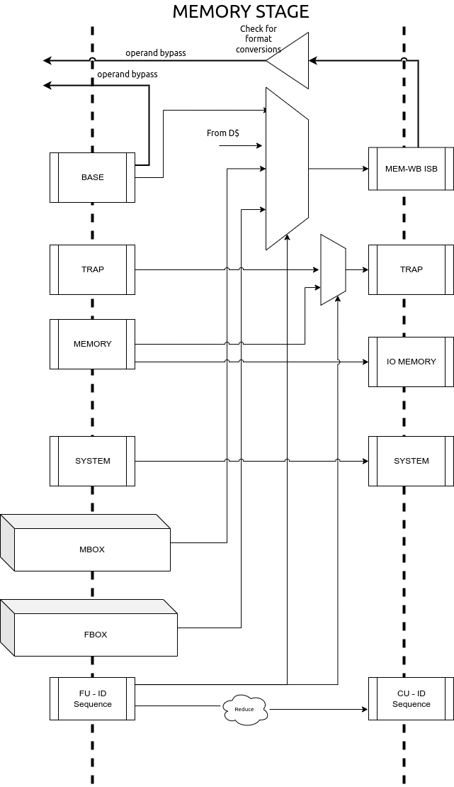
Fig. 6.8 Memory Stage of the Pipeline
The system instructions received from the previous stage are simply buffered into the next SYSTEM ISB, since these can only be performed in the write-back stage. For all other non-memory operations, once the functional unit responds with the correct result, it is enqueued into the MEM-WB ISB as shown in Fig. 6.8.
In case of memory operations, this unit waits for a response from the DMS. If the DMS response indicates that a trap occurred, then the instruction is tagged as a TRAP and the virtual address of the operation is captured for the mtval field. In case of cacheable load operations, the result from the DMS is directly fed in the MEM-WB ISB and is there on treated similar to the other arithmetic instructions.
In case of a floating point load operation, since the internal storage format is the custom recoded format, a boolean value (recode) is set in the packet from the previous stage. Operand forwarding is disabled for these values, as the bypass network only forwards values in the custom recoded format.
However, in case of store ops or non-cacheable ops, the DMS response indicates that a operations has been buffered and can only be committed from the write-back stage. In such situations, the instruction results are fed in to the IO-MEMORY ISB as shown in Fig. 6.8.
6.6. Write Back Stage [stage5.bsv]
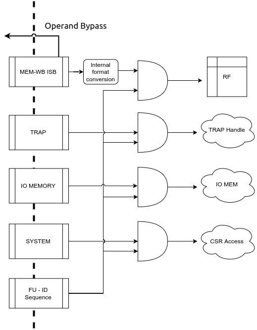
Fig. 6.9 Write Back stage of the pipeline
The write-back stage of the pipeline is where all instructions retire. By the time an instruction reaches this stage it has been narrowed down via some of the previous stages into one of the following categories of operations that can be performed in this stage:
SYSTEM: either xRET operations or CSR access operations.
TRAP: The instruction has encountered a trap during its operation in one of the previous stages.
BASEOUT: The instruction retirement includes a simple update to the registerfile
MEMOP: The instruction is either a cached store/atomic operation or an non-cached/IO memory op.
Each of the above have a unique ISB feeding in respective instructions to this module. This module uses the CUID from the previous stage, which maintains the order of instructions to find out which ISB must be polled for retiring/committing the next instruction as shown in Fig. 6.9
Operations which can take multiple cycles in this stage are : CSR operations if daisy-chain is more than 1 level deep; IO/non-cached Memory Operations may also take significantly longer in this stage to complete.
All other ops will take a single cycle to complete.
In case of a floating point load operation and the internal storage format is the custom recoded format, a boolean value (recode) is set in the packet from the previous stage. The loaded value in IEEE 754 format is converted into the custom recoded format before writing into the register file. A pictorial representation of the process for double precision is shown in Fig. 6.10.
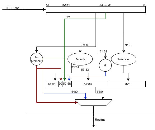
Fig. 6.10 Conversion from IEEE 754 to Custom Recoded format for Double Precision.
This module also instantiates the csrbox module, which hosts all the csrs and also the routines to perform a trap or an xRet operation. Certain csr interfaces are simply bypassed along this module so that they are exposed at the next hiegher level to rest of the pipeline and design.
6.7. Reset Sequence
The reset sequence of the core is quite simple. Once the core reset has been deasserted the following events start:
All sets of the instruction cache are invalidated
All sets of the data cache are invalidated
All the entries in the register file are set to zero
All entries in the bht and btb are reset and invalidated
As part of the reset sequence we ensure that stage-0 of the pipeline only generates the first PC when all the above are done. Since the above events always take a constant time, we use a counter to count the max number of cycles required by the above events, and only then the stage-0 logic is enabled.
6.8. Handling Re-directions
The execution stage and the write-back stage are capable of generating re-direction signals causing the entire pipeline to be flushed. The execution stage generates a redirection in the case of branch misprediction (if the BPU is enabled), or for control flow instructions that are taken (if BPU is disabled). The write-back stage on the other hand will generate re-directions for traps if an instruction (such as CSR ops) require a re-run of the subsequent instructions.
To account for this with little impact on timing and area, the pipeline implements epoch registers within each pipeline stage. The epoch register contents are not modified for a stream of instructions until a re-direction is generated from pipeline. The re-directions cause the epochs to toggle and thus, each stage will either process the instruction if the epoch values matches or else drop the instruction on a mis-match.
6.9. Instruction Latencies
The pipeline is optimized to provide a peak performance of one instruction per cycle. However, there are exceptions to this:
Assuming a cache hit, the Load to use latency is 1 for integer operations and 2 for floating point operations.
All CSR operations occur at the write-back stage. Considering a daisy chain architecture, a CSR operation can take anywhere between 1 to 7 cycles depending on the CSR being accessed.
All integer multiplication operations take 2 cycle(s).
All integer division operations take 32 cycle(s).
Floating Point division and sqrt operations take variable cycles to complete based on the inputs. The maximum number of cycles they can take is equal to the number of bits used to represent them e.g. 32 cycles for single precision.
Floating point add,mul,sub,fma and their variants are pipelined(based on the configuration provided). They can take multiple cycles to complete.